Schematic Terminal: Schematic terminal that follows the wire number rather than having a terminal number of its own. Schematic Terminal: Schematic terminal with terminal number. Schematic Child: Schematic secondary symbol that is related to a parent component. Must have a TAG1, TAG, or split TAG1 attribute. Schematic Parent: Schematic symbol is used as a stand-alone symbol or a parent component with related secondary contacts.

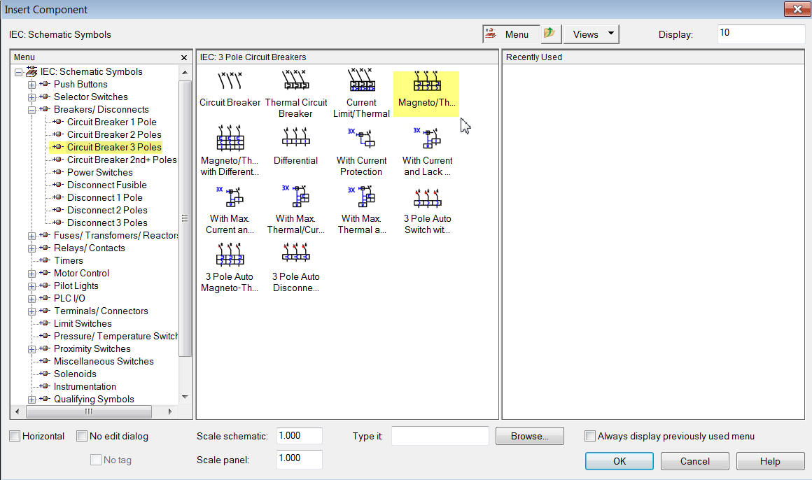
You can also select it from the Type it or Browse options in the bottom left-hand corner of the icon menu. You can add your new symbol to the icon menu. New symbols you create are inserted with the AutoCAD Electrical toolset Insert Component or Insert Panel Component commands. Selecting the objects allows the tool to track what standard attributes and wire connection points you already inserted. Each time you re-enter the Symbol Builder tool, select objects from within the Select Symbol/Objects dialog box. The AutoCAD Wblock command writes it to disk. You can also exit the command and use regular AutoCAD commands to edit or finish the symbol you are creating. You can exit the Symbol Builder command and re-enter it at any time. They break wires upon insertion, and appear in the bill of material and various component and wire connection reports. Symbols created or converted using Symbol Builder are fully compatible with AutoCAD Electrical toolset. You can insert additional DESCn attributes on your symbol and edit them with any attribute editing tool, but AutoCAD Electrical toolset does not process them.You can convert symbols or create custom components on the fly.

The attribute names are DESC1, DESC2, and DESC3 and generally appear on both parent/stand-alone and child contact symbols. You can insert three lines of description text up to 60 characters long. At insertion time the width of the symbol is determined by reading the locations of its wire connection attributes (attributes with name X?TERMn).Ī symbol can have hundreds of connection points and a terminal pin number attribute tied to each (use suffix codes beginning with "01" and ending with "ZZ"). Though it is not mandatory, it helps AutoCAD Electrical toolset determine the correct orientation for alignment with an underlying wire at insertion time. The AutoCAD Electrical toolset library symbols generally have their origin points centered between the first (or only) pair of wire connection point attributes.

A wire connection pigtail is mandatory when you insert a short pigtail at a wire connection point that has no other visible symbol geometry nearby since AutoCAD Electrical toolset must see something tangible on a symbol at a wire connection point. Pigtails can defeat the AutoCAD Electrical toolset SCOOT command and automatic wire numbering when two symbols with pigtails bump up against each other. Avoid putting wire pigtails on your new symbols.


 0 kommentar(er)
